


I. Description of the domestic hot water supply system
The solar system works to meet the needs of all hospital wards which currently use the central gas and oil-fired boiler room to obtain the heat necessary for the central heating system and the domestic hot water supply system. The boiler room is located in building B, a separate 3-storey building with a basement. The basic fuel used in boilers is GZ-50 natural gas while light fuel oil is treated as emergency fuel. The boiler room is equipped with two steam boilers and one water boiler made by Viessmann providing heat for central heating , domestic hot water preparation, ventilation and other technological requirements of the hospital building complex. The boilers are equipped with gas and oil burners made by OILON. Domestic hot water is stored in 4 hot water containers of 3 m3 each.
![]()

The solar system includes:
- 123 solar collectors (Geres –Asco G5 ) of the total absorption surface of 300.12 m2 and the capacity of 250.79 KW with the quality label of SOLARKEYMARK >> see
- 3 buffer tanks of the total volume of 12 000 l,
- Pre-heat tank of 1500 l,
- Controlling system (mixing pumps, double and three-way valves),
- 4 circulating pumps,
- Air separators,
- Legionella disinfection system pump,
- 2 anti-contamination valves,
- Heat exchangers ,
- 4 expansion vessels with safety valves,
- Cooling vessel of 500 l,
- New, pre-isolated central heating transmission pipes between the boiler room and the hospital of the total length of 491 m
- 17 manometers
- 3 electronic heat meters
- Insolation sensor measuring the real value of solar radiation
- Rotameters measuring the flow of solar liquid in individual sections of the system
II. Duration of the installation process
Works started on 18 September 2012 and finished on 17 December 2012.
III. Donors, Project Manager, investment value
The project involving the installation of a solar system on the local hospital building was launched and carried out by the Environment Department of the Poviat Starosty, which obtained the necessary funds from the following sources:
1. The Swiss-Polish Cooperation Programme – PLN 616 244.11 – 62.79 % of the costs

2. The Regional Fund for Environmental Protection and Water Management in Krakow – PLN 365 192.59 – 37.21 % of the costs

Thus the solar system was funded from subsidies in 100%. The only costs incurred by the Poviat were the ones related to the preparation of the project documentation.
The value of the works performed:
- Initial cost estimate - PLN 1 063 199
- After the tender - PLN 981 436
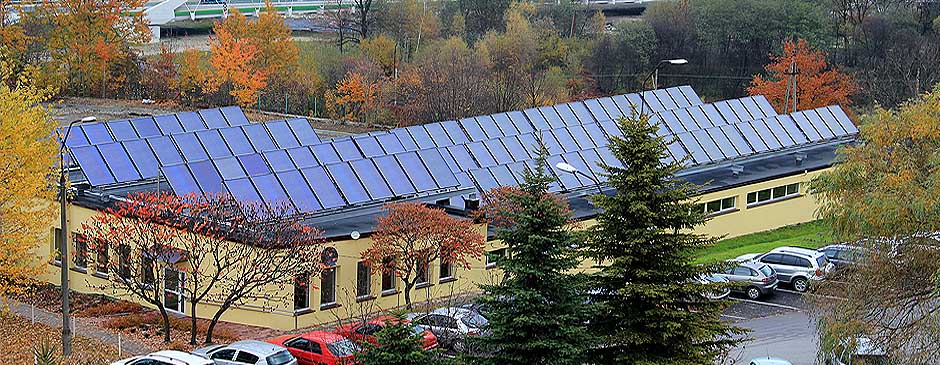
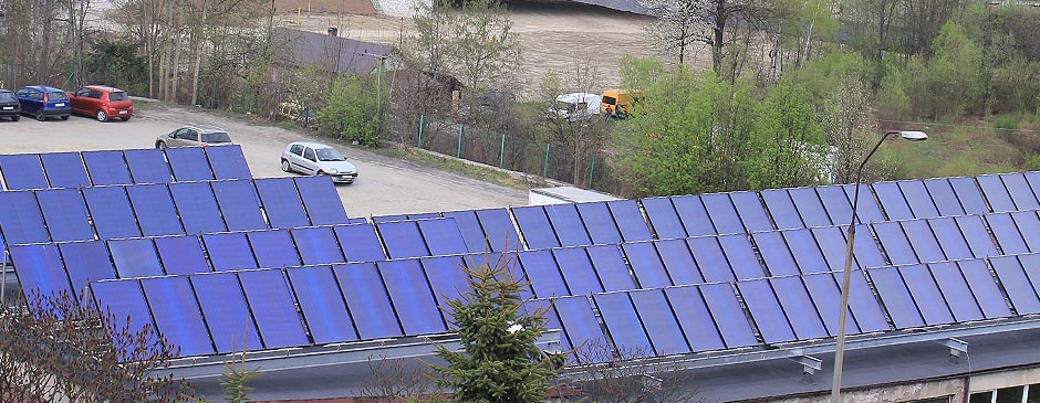
IV. Solar system installation - photos
")
a) July 2014


b) April - May 2013


c) On the acceptance day – 17 December 2012


d) Progress of works as of 7 December 2012


e) Progress of works as of 19 November 2012


g) Progress of works as of 19 November 2012


V. Description of the solutions adopted
The plan was to use the solar system to support the process of domestic hot water preparation, thus reducing the need to use conventional energy sources, which, in this case, was gas, and replacing it partially with solar energy.
Energy provided by solar panels was to be used to heat up domestic hot water for the complex of hospital buildings.
According to the initial design, the solar system was to be powered by the battery of 128 solar collectors of the total absorption surface of 296.96 m2. Eventually, 123 collectors of greater absorption surface were used by the contractor, where
1. the total absorption surface of all the collectors installed was 300.12 m2
2. the total capacity of all the collectors installed was 250.79 kW
3. the efficiency of all the collectors installed was at the level of 86%
Thus the appliances installed had better parameters than the ones adopted in the design documentation.
The solar collectors were placed on the support structure of the roof of building A housing the Patient Transport Service located next to the boiler room building using the fixing system developed by the producer of the appliances. The layout and connection of collectors aims to ensure optimum working conditions for the solar system.
The solar system has three separate circuits:
- the solar circuit which connects collectors with the WC1plate heat exchanger.
- two other circuits (water circuits) which connect, respectively, the WC1 plate heat exchanger with Z1 buffer tanks and the WC2 plate heat exchanger with the existing system used to prepare domestic hot water for the complex of hospital buildings
The major components of the solar system include solar collectors, buffer tanks, domestic hot water tanks, heat exchangers, circulating pumps and the equipment used to secure the solar and water systems.
Below you can find:
- the system flow chart
- the system diagram
- the projection of the collector location
- simulations of the solar system work
VI. Energy balance calculation and determination of the number of collectors
The size of the solar system, i.e. the number of solar collectors, was determined on the basis of calculations and the guidelines of the solar collector producer. The calculations were made for the summer season, i.e. the period with the greatest intensity of solar radiation lasting from June to August. The geographic location was taken into account and, consequently, the value of insolation per 1 m2 of the area where the system was located. In this case, the actinometrical station in Rabka is the closest to the location where the solar collector assembly is designed and the value of insolation equals 394,200 kWh/m2 here. This value is adjusted using the ratio that takes into account the orientation of solar collectors and their inclination angle relative to the ground level. In this case, collectors are pointed to the south and the inclination angle is 45 degrees, thus the ratio adopted is 0.94.
The solar system is powered by the collectors with the absorption surface of 2.32 m2 and optical efficiency of 83.5%. The calculations of the energy necessary to heat up domestic hot water for the local hospital building complex were made on the basis of the average consumption of domestic hot water per month, as provided by the user.
|
Average consumption of d.h.w. per month |
1 100.0 |
[m3/month] |
|
Initial water temperature |
10 |
[oC] |
|
Final water temperature |
55 |
[oC] |
|
Temperature differential |
45 |
[oC] |
|
Specific heat of water |
4.2 |
[kJ/kgK] |
|
Energy needed to heat up water |
57 612.55 |
[kWh/month] |
|
Energy obtained from the collector |
253.14 |
[kWh/month] |
|
System efficiency |
75 |
[%] |
|
Required number of collectors |
303.5 |
[items] |
|
Number of collectors selected |
128 |
[items] |
|
Demand satisfaction |
42 |
[%] |
The solar system designed includes 128 solar collectors.
The Contractor provided the energy balance calculation when submitting the bid >> see
VII. Characteristics of the system designed
The aim of the solar system is to obtain solar energy and transmit it to the heat exchanger, which in this case is water stored in the designed Z1buffer tanks. Energy may be transmitted using the WC1 plate heat exchanger. If the CN insolation sensor registers solar radiation above the radiation threshold level set in the controller, the P1circulating pump of the solar system will be switched on. If the difference between the temperature of the solar liquid in the collectors, indicated by the sensor mounted in the return pipe of the exchanger of the buffer tank loading circuit, and the temperature inside the buffer heater is greater than the temperature set in the controller, the P2 pump, which loads buffer tanks, will be switched on and the buffer tank loading process will begin. When the P2 buffer tank filling pump is turned on, the DZ1valve remains open while the DZ2 valve is closed. If the lower threshold of the temperature differential set is not maintained, the P2 pump will be switched off. The temperature in buffer tanks is limited using an electronic temperature limiter.
If the temperature value set is exceeded, the P1 solar system pump will be automatically switched off. The electronic temperature limitation value should be set at 70 °C. If the temperature differential between domestic hot water tanks and buffer tanks is greater than set in the temperature differential controller, the cycle of buffer unloading and water heating begins. The pumps working in the buffer unloading and pre-heater loading circuit are switched on and the DZ2 valve is opened while the DZ1 valve is closed. Buffer tanks will be loaded until the temperature set on the solar controller is achieved.
Adequate solar liquid circulation during buffer loading and unloading is possible thanks to the valve with an engine drive, TZM2, usually closed. As it is possible to electronically adjust the temperature limit in the Z2 domestic hot water tanks designed , the domestic hot water temperature limit is set at the level of 60°C.
During the system overheating periods the P5 pump should be switched on into the continuous work mode in order to protect domestic hot water against the proliferation of Legionella. The water in the buffer system will be topped up by the existing cold water supply system using softened water, supplied automatically thanks to the SYR system filling valve. The amount of the water supplied is measured by the PoWoGaz cold water meter.
The pre-heated water from the Z2 domestic hot water tank will be sent to the existing domestic hot water supply system.
The solar system includes insulated solar tubing. The solar liquid circulating between the solar collectors and the WC1 plate heat exchanger is the water solution of propylene glycol with additives.
The liquid in two other circuits is water.
This is a pressure system where the circulation of heat carriers is forced by circulating pumps. The system is secured against excessive pressure growth by safety valves and expansion vessels.
The tubing of the solar system runs on the roof of the Patient Transport Service building and it will be led into the technological channel connecting buildings A and B.
Using the channel, the solar tubing will be connected to the room housing buffer tanks, the domestic hot water tank together with the equipment securing it, circulating pumps, plate heat exchangers and the automation system for the solar system designed.
The dimensioning of the solar system was made on the basis of the guidelines provided by the solar panel producer. The tubing diameter selected makes it possible to achieve the required flow which enables the system venting.
Moreover, in order to vent the system, automatic venting valves preceded by cut-off valves were designed at the outlet of each group of solar collectors. An automatic venting valve is to vent the solar system only at the moment of filling it and it should ensure that the solar system is closed while in operation. Otherwise, glycol may evaporate from the solar liquid inside the system.

Symulacja - Szpital Sucha Beskidzka.pdf
pobrań: 437
usytuowanie kolektorów slonecznych.pdf
pobrań: 374